|
|
|||||
| Featured Articles/Orthogonal Illumination Maps |
|
|
IntroductionPut simply, orthogonal illumination mapping is a texture-based multi-pass rendering technique for performing hardware accelerated lighting calculations per-pixel rather than per-vertex. It has a number of advantages: it is simple, geometry-independent, and fast on today's commodity graphics cards. Rather than go directly into the technique, let me motivate the problem a bit. MotivationHow many times have you rendered your terrain database at full geometric resolution and been stunned by the picture, but dismayed that it took 20 seconds per frame? It has happened to me a lot. :-) There are a number of excellent techniques for mesh simplification that seek to reduce the number of triangles we have to render, but this typically has a direct and immediate impact on the quality of the lighting in OpenGL. Even small variations in height can produce wonderful visual cues when illuminated (ala bump-mapping), but these small variations are typically the first to go in mesh simplification. Since OpenGL lighting is performed per-vertex, we have a real problem reducing the geometry without negative impact on the lighting. Well, that leaves us with a few alternatives:
The TechniqueAssuming you chose the third option above, you'll want to know how to go about implementing it. I guess we might as well get to some of the bad news at this point. This technique (as I have implemented it) requires 1 pass for ambient, 6 passes for diffuse, and 1 pass to blend in a color texture. Don't panic! Even with 8 passes, it's still a LOT faster than rendering all the geometry. In this new world order of multitexturing, many of these passes can be collapsed into a single pass. With the worst news safely behind us, let's see the technique. First with a simple picture equation, then in prose.
So the basic idea is to perform diffuse illumination (L dot N) just like you would do per-vertex using OpenGL lighting, but instead, do it per pixel. The components of L are premultiplied with the light color and the material properties and specified as the current color, while the components of N are each turned into textures. The dot product is performed by using a TexEnv of MODULATE for the multiplicative operations and blending for the (signed) additive operations. This has the desired effect of moving the whole dot product calculation into the fragment processing portion of the OpenGL machine. The trickiest part of this technique is the fact that the dot product is the sum of signed values, and textures and colors are unsigned in OpenGL. This requires careful formulation of the equation to avoid negative values. It is helpful to think first of how this technique would be implemented if signed colors, textures, and framebuffer contents were allowed, then work backwards to try to achieve the same result given our actual constraints. So if the burden of unsignedness were lifted, we would formulate this dot product by defining a signed luminance texture for each of the normal components, and the algorithm would look something like this: If OpenGL colors, textures, and color buffer held signed values:
So the technique is pretty straightforward for this hypothetical variation of OpenGL. The task now is to come up with a method for getting the same result with the real OpenGL. First, we know we cannot have signed textures, so instead of signed luminance textures of Nx, Ny, and Nz, we use unsigned luminance textures of NposX, NnegX, NposY, NnegY, NposZ, and NnegZ. Next, we cannot have negative color buffer contents, so we need to make certain to perform all operations that have an additive effect on the color buffer first and all operations that have a subtractive effect on the color buffer last. We also have to deal with the signedness of Lx, Ly, and Lz, but at this point, let's assume a simple case of Lx, Ly, Lz > 0, and see what the order of operations would be to generate the composite shown above. If EXT_blend_subtract is supported:
If EXT_blend_subtract is NOT supported: (try to fake it)
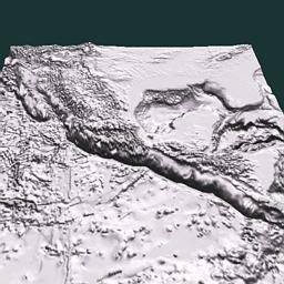
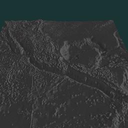
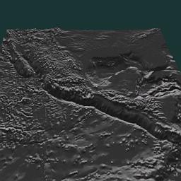
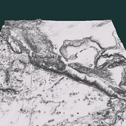
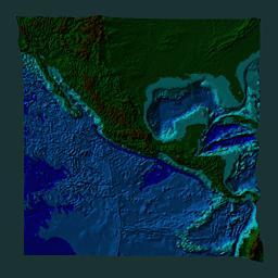
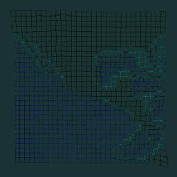
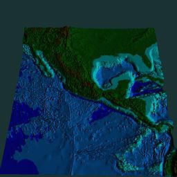
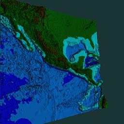
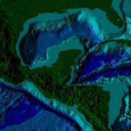
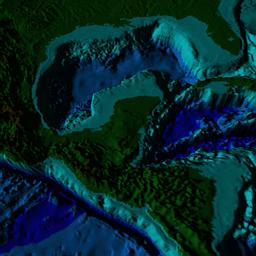
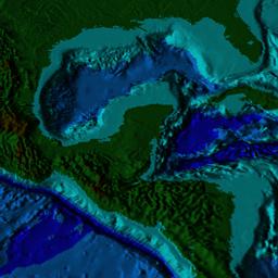
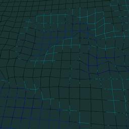
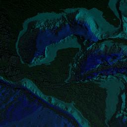
It should also be noted that the ambient pass comes first when faking the subtractive blend. It is done to help minimize the error of this approximation. Also, the technique here is not adapted for multitexuring, but such adaptations would not be difficult for a given set of functionality (ie number of texture units, tex_env extensions, and blending modes). ResultsAll the illustrations here were generated using the NVIDIA drivers for linux on a Riva TNT. The demonstration code is GLUT and has been verified to work under Irix and Win32 as well. Because the Riva TNT does not support subtractive blend, all of the examples here were created using the hack mentioned earlier. If you do the math, you will discover that this hack causes the darker areas to be a little lighter than they would otherwise be. I have also verified this visually on SGI machines (which support subtractive blend) and by toggling the demo program between OpenGL lighting and orthogonal illumination mapping. The demo program uses etopo5 (earth topography database, 5 minute resolution). The textures are generated at full resolution while the geometry is subsampled by 16 in both I and J. Obviously a more sophisticated mesh simplifier would produce better results, but the naive mesh simplification is still valid (and very easy to implement). So, we will start with some subjective comparisons on images produced by the demo program and then look at some of the numbers.
Now for the numbers. These results were generated on a couple of machines I have at home. Machine A is a celeron 300A that is overclocked to 450 MHz. It has a Diamond Viper 770 (TNT2) board with 32 MB of memory. It also has 128 MB of main memory. Machine B is a pentium 200MMX with a Creative Graphics Blaster (TNT) board with 16 MB of memory. It has 96 MB of main memory. Values in the table are frames per second.
The 6-pass OIM test removes the pass for NnegZ as a simplification for height field data. The final pass for blending in the color texture is omitted from these tests as well. DownloadsIf, after all this, you're actually interested enough to run the demo program for yourself and maybe tinker with the source a bit, you'll need to download it from one of the following links: Source with Etopo5: (11 MB) thesis.zip from preferred high-bandwidth server: [http] [ftp] thesis.zip from lower-bandwidth server: [http] [ftp] NOTE: WinZip corrupts the etopo5.bin file in the .tar.gz archive. If you are using WinZip, get the .zip file! thesis.tar.gz from preferred high-bandwidth server: [http] [ftp] thesis.tar.gz from lower-bandwidth server: [http] [ftp] For the source only: (really small) thesis-source.tar.gz thesis-source.zip ConclusionThis document was thrown together rather quickly, but perhaps it will serve well enough as an introduction to Orthogonal Light Maps for now. It will undoubtedly undergo some iterations to improve the presentation, correct errors and refine the techniques. Until I have more information available, please feel free to contact me at cass@r3.nu if you have specific questions or interests regarding this technique. As you might have surmised by the link names above, I am trying to synthesize this work into a thesis, so if you have any information about similar techniques please drop me an email. AcknowledgementsA big thanks to Mark Kilgard for some corrections and refinements to the technique as presented in the original posting of this article. (You can find the specifics of his enhancements in the demo source.) Thanks also to Michael Gold and David Gould for helping me verify the Win32 versions worked. Finally, thanks to Robert Moorhead who got me started in computer graphics and is guiding me through the development and documentation of this work.
|
|
|||||||||||||||||||||||||||||||||||||||||||||||||||||||||||||||||||||||||||||||||||||||||
|
|
|||||||||||||||||||||||||||||||||||||||||||||||||||||||||||||||||||||||||||||||||||||||||||
